



30-10-2026
The new rules in five examples
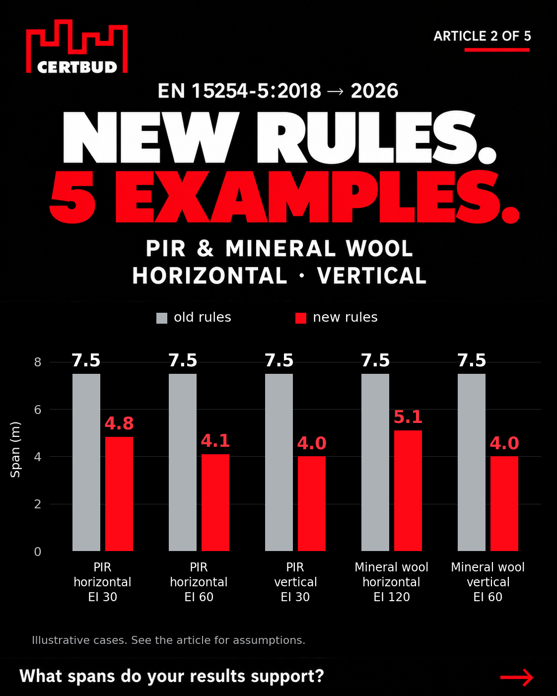
A comparison of the rules for determining the maximum span of sandwich panels under EN 15254-5:2018 and EN 15254-5:2026 — Examples.
Article 2/5 in the series discussing the new rules for assessing sandwich panel fire resistance results
Drawing on our many years of experience as a laboratory testing sandwich panels and preparing test and classification reports covering the direct and extended application of test results, we see many questions and uncertainties surrounding the correct interpretation and practical use of the results obtained.
In this article, we discuss the application of EN 15254-5:2018 and EN 15254-5:2026, focusing on the differences in how the maximum permissible span of sandwich panels is determined. We hope this information will help sandwich panel manufacturers correctly determine and offer panel spans for their projects within the scope that can be substantiated by test results.
The examples below will help assess whether the range of solutions offered on the basis of EN 15254-5:2018 can be retained once EN 15254-5:2026 takes effect, or whether it will need to be reviewed and adapted to the new requirements.
In all the examples, the sandwich panels tested had a span of 3.0 m, and the test results established the following:
- deflection not exceeding 100 mm,
- the possibility of proportionally increasing the clearances that allow the wall to expand freely during heating [5].
- a fire resistance period corresponding to simultaneous compliance with the integrity (E) and insulation (I) criteria.
The deflections stated in the examples are the maximum values measured during the test. The calculated maximum spans have been rounded down to whole centimetres to avoid overstating the calculated limit. This is the presentation method adopted here, rather than a universal requirement of the standard.
It was also assumed that direct application of the test result allows the span to be increased by 1 m, to 4 m.
Under EN 15254-5:2018, extending the span to 7.50 m required a time margin achieved in the test of at least 35% of the period associated with the target class, but no less than 10 minutes. The notation “max” in the calculations means selecting the greater of these two values. [3]
Under EN 15254-5:2026, the time margin is converted into additional metres using the rule applicable to the core type, panel orientation and — for horizontal PIR panels — the target class. The increase is calculated from the tested span, which is 3 m in the examples presented here.
If the calculations under EN 15254-5:2026 give a span of less than 4 m, the 4 m span permitted by direct application of the test result can be retained.
EXAMPLE 1
PIR sandwich panels, horizontal orientation, fire resistance test result of 41 minutes, maximum deflection of 80 mm.
EN 15254-5:2018
The calculated time required to adopt a maximum span of 7.50 m is:
tmin = 30 + max(0.35 × 30; 10) = 30 + 10.5 = 40.5 min
The test result of 41 min is greater than the calculated time, so a maximum panel span of up to 7.50 m can be adopted.
EN 15254-5:2026
For the panels tested in this example (with a span not exceeding 5 m), where the time achieved in the test does not exceed 45 min, a reduction of 6 min/m is applied.
Calculation of the maximum span:
LEXAP = 3 + 41 – 306 = 4.8333… m
For the panels tested, a fire resistance class of EI 30 and a maximum span of up to 4.83 m were obtained.
If the maximum panel span were to be 5 m, with a test time of 41 min, the time used to determine the fire resistance class would be: 41 − 6 × 2 = 29 minutes.
Thus, at a maximum span of 5 m, the fire resistance class is reduced from EI 30 to EI 20 and EI 15.
EXAMPLE 2
PIR sandwich panels, horizontal orientation, fire resistance test result of 82 minutes, maximum deflection of 95 mm.
EN 15254-5:2018
The highest fire resistance class in this case is EI 60. The minimum time required to extend the span to 7.50 m is:
tmin = 60 + max(0.35 × 60; 10) = 60 + 21 = 81 min
The test result of 82 min meets this requirement.
EN 15254-5:2026
Under this standard, EI 60 is a class above EI 45 minutes, so the maximum span was calculated using the following formula (the so-called 20 min/m rule):
LEXAP = 3 + 82 – 6020 = 4.10 m
The results obtained allow a fire resistance class of EI 60 and a panel span of up to 4.10 m to be declared.
Although the test result in EXAMPLE 2 was twice that in EXAMPLE 1, it should be noted that declaring a higher fire resistance class entails a reduction in the maximum panel span.
EXAMPLE 3
PIR sandwich panels, vertical orientation, fire resistance test result of 41 minutes, maximum deflection of 90 mm, fire resistance class EI 30.
EN 15254-5:2018
To allow the span of the sandwich panels in this arrangement to be increased to 7.50 m, the following condition must be met:
tmin = 30 + max(0.35 × 30; 10) = 30 + 10.5 = 40.5 min
The test result meets this requirement.
EN 15254-5:2026
For vertically oriented PIR sandwich panels, the 35 min/m rule must be applied:
LEXAP = 3 + 41 – 3035 = 3.3142… m
The result allows the panel span to be increased to 3.31 m. However, direct application of the test result can be used to increase the span to 4 m.
EXAMPLE 4
Mineral wool sandwich panels, horizontal orientation, fire resistance test result of 162 min, deflection of 70 mm, fire resistance class EI 120.
EN 15254-5:2018
To allow the span of the sandwich panels in this arrangement to be increased to 7.50 m, the following condition must be met:
tmin = 120 + max(0.35 × 120; 10) = 120 + 42 = 162 min
The calculated result exactly meets the threshold required by the standard.
EN 15254-5:2026
For the sandwich panel arrangement considered here, the 20 min/m rule applies within the span extension range under consideration, up to 6 m:
LEXAP = 3 + 162 – 12020 = 5.10 m
This allows the span to be increased to 5.10 m.
EXAMPLE 5
Mineral wool sandwich panels, vertical orientation, fire resistance test result of 81 min, deflection of 50 mm, fire resistance class EI 60.
EN 15254-5:2018
To allow the span of the sandwich panels in this arrangement to be increased to 7.50 m, the following condition must be met[3]:
tmin = 60 + max(0.35 × 60; 10) = 60 + 21 = 81 min
The test result meets the standard’s condition, so the panel span can be increased to 7.50 m.
EN 15254-5:2026
For this arrangement, the 35 min/m rule applies in accordance with the standard:
LEXAP = 3 + 81 – 6035 = 3.60 m
In this example, it is more favourable to use direct application of the test result, which allows the span to be increased to 4 m.
SUMMARY OF THE RESULTS FROM THE EXAMPLES
The table below summarises the results obtained in the examples.
Example no., core, tested orientation, test duration achieved | Class under EN 13501-2 | Maximum span under EN 15254-5:2018 | Maximum span under EN 15254-5:2026 | Maximum span adopted in 2026 |
|---|---|---|---|---|
1. PIR, horizontal; 41 min | EI 30 | 7.50 m | 4.83 m | 4.83 m |
2. PIR, horizontal; 82 min | EI 60 | 7.50 m | 4.10 m | 4.10 m |
3. PIR, vertical; 41 min | EI 30 | 7.50 m | 3.31 m | 4.00 m, based on direct application of test results |
4. Mineral wool, horizontal; 162 min | EI 120 | 7.50 m | 5.10 m | 5.10 m |
5. Mineral wool, vertical; 81 min | EI 60 | 7.50 m | 3.60 m | 4.00 m, based on direct application of test results |
Source: prepared on the basis of the cited documents.
Conclusions for sandwich panel manufacturers
In all five examples analysed, applying the new rules for determining the maximum span of sandwich panels reduces the permissible span for the highest EI fire resistance class achieved. This does not mean that the behaviour of the tested wall under fire conditions has changed; it limits the range of spans that can be substantiated by the test results obtained.
A properly prepared offer specifying the maximum panel span should take account of the fire resistance class, core type, installation direction and tested panel span together. The span achievable under the rules for direct and extended application of test results must also be verified. It should be remembered that, in addition to calculations carried out in accordance with the relevant standards, the panel fixing arrangement must be assessed, particularly the number and loadbearing capacity of the fasteners under fire conditions, as well as the loads arising from the panels’ self-weight.
In practical terms, manufacturers should first compare the spans required for current and planned projects with the scope that can be substantiated by their existing test results. Where discrepancies are identified, it may be necessary to restrict the declared field of application of the product or carry out additional tests planned specifically for the intended applications. This analysis is best carried out before making further commitments concerning the required EI fire resistance class and maximum panel spans.
All articles in the series
New rules for assessing the fire resistance of sandwich panels
1 of 5 — What changes for manufacturers
2 of 5 — The new rules in five examples — you are reading this article
3 of 5 — Facing colour and the scope of classification — in preparation
4 of 5 — Where the new requirements come from — in preparation
5 of 5 — Manufacturers’ frequently asked questions — in preparation
Glossary — explanations of abbreviations and terms
References
- EN 14509:2013. Self-supporting double skin metal faced insulating panels — Factory made products — Specifications. Edition consulted: PN-EN 14509:2013-12, English version; clauses 2, 5.2.4.2, C.2.2, C.2.4.1, E.3.3, ZA.1.1 and ZA.2.1.
- EN 13501-2:2023. Fire classification of construction products and building elements — Part 2: Classification using data from fire resistance and/or smoke control tests, excluding ventilation services. Edition consulted: PN-EN 13501-2:2023-09, English version; clauses 2, 6.3, 6.7, 7.1, 7.5 and Annex A.
- EN 15254-5:2018. Extended application of results from fire resistance tests — Non-loadbearing walls — Part 5: Metal sandwich panel construction. Edition consulted: PN-EN 15254-5:2018-06, English version; clauses 3, 4, 5.2.2.1, 5.2.4.2, 5.3.1, Table 4 and Annex B.
- EN 15254-5:2026. Extended application of results from fire resistance tests — Non-loadbearing walls — Part 5: Metal sandwich panel construction. Edition consulted: BS EN 15254-5:2026; Foreword, clauses 3, 5.2.2.1, 5.2.3, 5.2.4.2, 5.3.1, 5.4, Tables 4 and 5, and Annex B.
- EN 1364-1:2015. Fire resistance tests for non-loadbearing elements — Part 1: Walls. Edition consulted: PN-EN 1364-1:2015-08, English version; clause 13.3 and Annex B, clause B.6.3.
